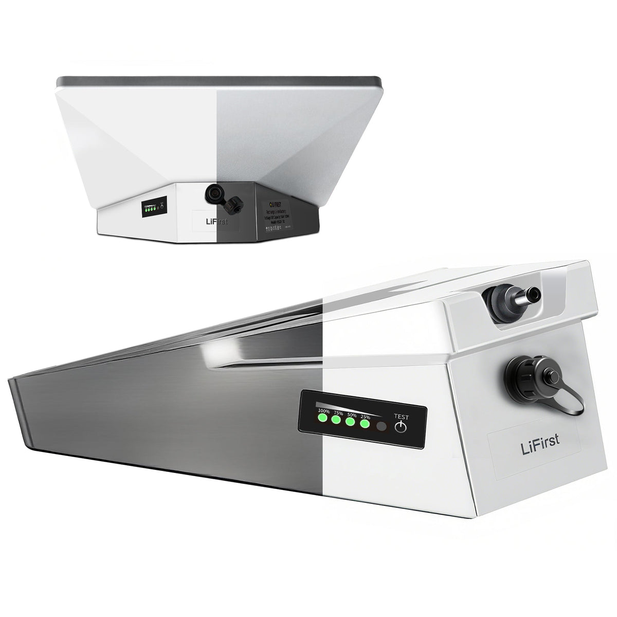
Version — Technical Deep Dive into Starlink Mini’s Power System
Starlink Mini is more than a compact satellite terminal—its internal engineering features a highly optimized power delivery system designed for fast booting, efficient idle usage, and stable peak throughput. For professionals using Starlink Mini in demanding environments, understanding its electrical behavior is crucial.
This article provides a technical breakdown of the Mini’s power requirements, measured consumption patterns, thermal characteristics, and how external DC sources can optimize field performance.
1. The Starlink Mini Power Input System Explained
Recent teardown analyses and field measurements show:
✔ Input Voltage Range: 20V–56V (internally regulated)
The Starlink Mini accepts a wide input range, but operates internally at a stepped-down regulated voltage.
The Sweet Spot: ≈ 25–28V DC input
(Closest to the original Starlink Mini charger: 25.2V / 3A)
✔ Peak Power Draw (Booting & Orientation)
During boot:
-
Power spike: 55–65W
-
Duration: 10–15 seconds
-
Caused by phased array initialization + thermal calibration
✔ Nominal Power Draw (Connected)
Typical steady usage:
-
32–38W in standard networking mode
-
Lower in idle mode if no active traffic
This is why a 99Wh battery can power it for approximately 3–5 hours depending on environment and workload.
2. Why Starlink Mini Is More Efficient Than Standard Dishy
Compared to the full-size Starlink terminal:
| Feature | Standard Dishy | Starlink Mini |
|---|---|---|
| Peak power | 110W+ | ~60W |
| Idle power | 45–55W | 20–25W |
| Voltage profile | 48V PoE | 25.2V DC |
| Thermal load | High | Much lower |
Mini achieves this with:
-
Lower array element count
-
Optimized RF front-end
-
More efficient beam steering
-
Better low-power idle mode
This makes it highly suitable for portable power banks and off-grid setups.
3. Runtime Behavior: How Power Consumption Changes in Real Use
Field engineers have documented consumption variations depending on:
✔ Environment
-
Cold environments: higher power to maintain optimal RF temp
-
Hot environments: power consumption rises due to cooling cycles
✔ Network load
-
Heavy upload usage slightly increases draw
-
Idle device in online state consumes far less
✔ Dish orientation changes
-
Small power spikes occur when correcting angle toward satellites
✔ Firmware updates
-
Some updates temporarily increase power while optimizing thermal states
Knowing these variables helps selecting the right power supply capacity.
4. The Importance of Clean and Stable DC Power for Starlink Mini
Starlink Mini is sensitive to:
-
Voltage sag under high load
-
Ripple/noise from cheap DC adapters
-
Slow response DC regulators
Voltage dips may cause:
-
Reboots
-
Packet loss
-
Dish realignment delays
Optimal DC Specification
-
Output Range: 15V–21V, ≥4A
-
Peak-safe headroom to handle boot surge
-
Low ripple to maintain RF stability
This is why high-quality dedicated batteries outperform general-purpose power stations for Starlink Mini.
5. Heat & Efficiency: How Temperature Affects Starlink Mini Power Use
Starlink Mini operates best between:
-
0°C – 35°C
In hot outdoor environments:
-
RF front-end heats up, causing autonomous cooling
-
Power consumption increases by 10–20%
-
Throughput may drop if thermal throttling activates
Recommended thermal optimization:
-
Elevate device from hot surfaces
-
Provide airflow around the backplate
-
Avoid placing battery directly under the Mini (heat stacking)
6. How External DC Batteries Enhance Performance & Runtime
Most Starlink Mini users now adopt DC-to-DC optimized batteries instead of AC power stations, because:
DC Power Advantages
-
Higher efficiency (no AC inversion loss)
-
Smaller temperature rise
-
Longer runtime from same Wh capacity
-
Lower ripple, more stable RF behavior
Recommended configurations:
-
99Wh battery → 3–5 hours (portable missions)
-
180–200Wh battery → 7–10+ hours (field teams, camping)
-
Solar + DC battery → multi-day operation
A proper DC output aligned with Starlink Mini’s preferred range prevents boot surges from causing shutdowns.
7. Building a High-Stability Field Power System (Engineering Reference)
Ideal off-grid setup includes:
-
Starlink Mini
-
DC battery with 18–21V regulated output
-
Strain-relief cable system
-
Thermal airflow spacing
-
Optional 60–120W solar panel
-
Waterproof cable sleeves
This configuration is widely used by:
-
Surveying teams
-
Rescue operations
-
Construction supervisors
-
Off-grid environment researchers

0 comments